Series and parallel circuits
The components of an electrical circuit can be attached in one of two forms,
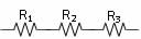 |
As the name suggests these components are attached one after the other in a continuous chain which starts and ends at a power source. The charge flowing (electric current) in the circuit must flow through each resistor one after the other. There is only one path for the charged electrons to take in a series circuit. |
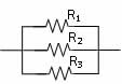 |
This type of connection allows different paths for the current to flow along, i.e. the current can split to flow along two or more parallel paths. The charges flowing in this type of circuit reach the junction or splitting point in the wires and can then flow along each path. |
The resistance of a resistor is affected by a number of variables. You should explore these variables using the interactive app Resistance in a wire. You can download this Java app from the Interactive learning guide.
Picture this model that might help you to understand electrical circuits and electricity flow…
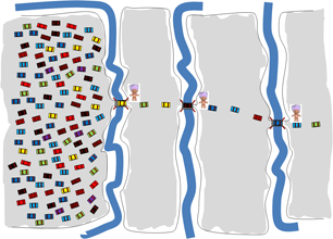
Imagine a really wide, multi-lane road that narrows each time it approaches a bridge. At each bridge there is a toll collector who must be paid before you can cross the bridge and proceed. The bridges represent the resistors in an electric circuit while the multi-lane road represents a conducting lead. When the flow of cars, equivalent to the electric current in a circuit, reaches the bridge they must slow down, pay their toll and then cross the bridge. The payment of the toll is like the charges losing their energy as they pass through a resistor. In a series circuit of three resistors, we can imagine the scene looks a bit like the diagram shown below:
|
aaaa |
The bridges are like resistors in a circuit. In a series circuit the resistors lay one after the other. The current (no. of cars) is the same over each bridge, i.e. the same in all parts of the circuit. The toll being paid is equivalent to the energy lost in passing through the resistor. To reach the other end and complete the circuit, each car must divide its money (energy) so that each toll can be paid. The flow of cars (current) is restricted by the number of resistors (bridges). |
 |
|
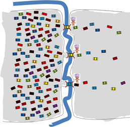
In this example the bridges are in parallel. You will notice that there are more cars flowing along the road (a larger current), but each car has only the one bridge to cross, so they pay a hefty toll, giving up ALL their energy as they cross the bridge. This means the voltage for each resistor (bridge) is the same when resistors are attached in parallel and the resistance of parallel resistors is less than for the same resistors connected in series. |
Some important differences in Series and Parallel connections.
Series |
aaaa |
Parallel |
Current is the same in all parts of a series circuit, i.e. the current flowing from the power supply, the total current, IT, is the same as the current through each resistor, i.e. IT = I1 = I2 = I3 |
|
The total current splits to flow along each parallel path, with the most charge flowing through the smallest resistor. The total current flowing into the circuit is equal to the sum of the currents which flow along each parallel path, i.e. IT = I1 + I2 + I3 |
The total voltage dropping over a series connection is equal to the SUM of the voltage drops over each resistor attached in the series circuit, i.e. VT = V1 + V2 + V3 Series circuits are broken if one resistor in the circuit breaks the circuit. Celebratory light strings are often partly series which means that if one globe blows then a portion of the light string will no longer light up. This is a nuisance to the person who must check each bulb until the failed component light is located and replaced. Series circuits are rare in the home. |
|
The voltage drop over a parallel circuit is the same for EACH resistor attached in the parallel circuit, i.e. VT = V1 = V2 = V3 In your home electric circuit every power point or light socket delivers electricity at 240 V because the electrical circuit at home is a parallel circuit. So is a power board you might add to expand the number of appliances you can connect to a single power outlet.
With a parallel circuit electricity can independently be accessed at every path in the circuit.
|
The total resistance of a series circuit is equal to the sum of the individual resistors in the circuit, i.e. RT = R1 + R2 + R3 |
|
The total resistance of a parallel circuit is LESS than the smallest resistor in the circuit |