Experiment - Series and parallel circuits
In this experiment you will examine the difference between series and parallel circuits. The most common place you will encounter electric circuits is across them. This activity will allow you to explore a model circuit and decide whether these light circuits are connected in series or in parallel.
Remember to perform your risk assessment before commencing this experiment.
Design any tables you will need to make sure your data collection is able to be clearly communicated to others before you commence your experiment.
Aim |
To examine the voltage and current flow in a series and parallel circuit of resistors. |
Apparatus (Equipment) |
To examine the voltage and current flow in a series and parallel circuit of resistors. 2 x 5 ohm or 10 ohm fixed resistors 1 x 0 to 5A ammeter 1 x 0 to 12V voltmeter 1 x 12V DC power supply Suitable conducting leads to connect circuit 2 x tapping key switches |
Method |
Part 1 - Series: Attach the components together in a circuit as shown in the following diagram. Note: The voltmeter will be moved during the experiment. The positions for attaching the voltmeter are shown. You can also try moving the ammeter to different points in the circuit. Remember, ammeters are attached in the circuit in series. 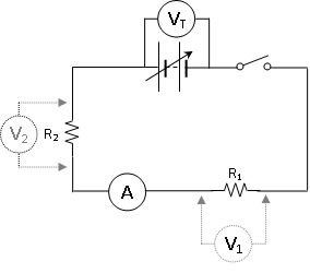
The variable power supply was set to 4V. (Your teacher may vary this value depending on the equipment you are using). The switch was closed and the readings on the ammeter and voltmeter were recorded in a table of results. This was repeated with the power supply set to 8V, and then again at 12V. The results were recorded and carefully analysed to note any relationships that are evident. Part 2 - Parallel: Attach the components together in a circuit as shown in the diagram below. Note: The voltmeter and ammeter will be moved during the experiment. The positions for attaching the meters are shown. 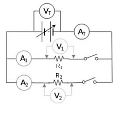
The meters were positioned first to measure the voltage of the power supply and the total current flowing into the circuit.
The meters were then moved to collect readings for the voltage applied, and current flowing through, R1.
This was then repeated and the values for R2 recorded.
The results were tabulated and then analysed and discussed.
A conclusion was then written.
|
Questions
- What relationship did you notice with the voltages when you had the resistors attached in series? Does this observation support the electric light circuit in the home being a series circuit?
- What does this voltage reading suggest about the way energy is being transformed by the circuit?
- Can you see any relationships between the value of the currents and voltages read by the different meters?
- Compare the current and voltage through the resistors when they are attached in series compared to when they attached in parallel. Does this support the electric light circuit in the home being a parallel circuit?
- Analyse your results considering especially the relationships to show how the series and parallel are similar and different.
- In which type of circuit, series or parallel would the electrical energy be transformed to other types of energy fastest? Describe your observational evidence that supports that identification.