Starting with circuit 1, construct the circuit and carry out the trial as shown below: Circuit 1. 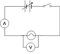
Circuit 2. 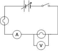
Circuit 3. 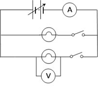
The variable power supply was set to 2 V. The circuit was turned on briefly by closing the switch to complete the circuit and observations of the meter reading made. This was repeated for each further setting on the variable power supply until 12 V was reached or till one of the meters deflected full scale. For circuit 2 move the voltmeter so that you take readings across both light globes. Careful observations on the appearance of the light globe(s) and any reading on the ammeter were made and recorded. Design a table that would enable easy communication of your observations to someone else not doing this investigation. The observations were recorded. This was repeated for each of the other circuits, i.e. 2 . Consider whether this is the best design for the circuit. Both circuits 1 and 2 are called series circuits. Design a parallel circuit using two light globes. Check the paper circuit design with your teacher, build the circuit have it checked for safety with your teacher and operate it. How does the voltage dropped across each light globe compare to the same setting range on the power supply? The results were recorded, analysed, and then a conclusion written.
|